9:20 AM 3rd-Party SFP+ Transceivers Testing and Verification |
|
Overview
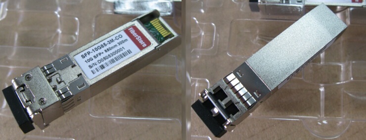
As the technology and market of optical transceivers continue to mature, 3rd-party SFP+ optical transceivers, especially the 10GBASE SR SFP and 10GBASE-LR SFP modules which are now widely used in optical transmission solutions, In order to ensure compliance, 3rd-party SFP+ optical transceivers need to be tested and verified before inserting to the device. This paper will talk something about the testing and verification methods of 3rd-party SFP+ transceivers. Why Are 3rd-Party SFP+ Transceivers So Popular?
Nowadays, people prefer to use 3rd-party SFP+ transceivers rather than officially-branded's. The increasing market demands of 3rd-party transceivers illustrate the point. As an example, there is absolutely no difference between an Cisco SFP-10G-SR transceiver and a 3rd-party 10GBASE-SR SFP module. As long as 10GBASE-SR SFP+ transceivers meet the international standards, there is no question of compatibility between SR SFP and Cisco switches. Actually, most "third party" SFP+ transceiver is made and assembled in exactly the same plants assembling officially-branded SFP+. In addition, it is very, very unlikely that a transceiver module will damage a switch. The primary benefit is the cost savings. The difference in price often exceeds 80 percent or more (Click to see SFP-10G-SR price). Because transceiver costs are a significant part of the total system cost, it is important for designers to minimize these costs. With the significant savings, designers can re-invest and make their designs better. This is why 3rd-party transceivers are more and more popular with users. Testing & Verification Are Necessary
There are methods to test and verify the 3rd-party transceiver modules, but it's not always as easy as it seems. It was easier when the entire network was owned by a single company. As long as the system worked, there was no need to test all the subcomponents extensively. Now, you have so many components from so many different suppliers that you'll need a test strategy to ensure that all components will meet the system level requirements. Here's what you need to know if you're considering testing and verifying in today's world. Test for an Acceptable Bit-Error Ratio
In a digital communications system, you must always operate within an acceptable bit-error ratio (BER). This is true whether you are testing an interface bus in a laptop computer or a telecommunications link. In general, when you're testing in a digital communications system, it should be no more than one error in 1012 bits. If the desired BER is not reached, it must be determined if the problem is in the transmitter, receiver, or both. Test to Determine Interoperability With a Worst-Case Transmitter
Network specifications should determine if the worst-case transmitter will interoperate with a receiver. Transmitters should also have a signal sufficient enough to support the worst-case transceiver. Determine the Minimal Power Level & Jitter Level
A receiver will need to achieve a minimum power level to achieve the BER target. The level achieved will dictate the minimum allowed output power. Likewise, if the receiver can only achieve a certain level of jitter, this will be used to define the maximum amount of jitter that can be received from the transmitter without malfunctioning. Transmitter parameters may specify the wavelength and the output waveform shape. Try Performing the Optical Eye-Mask Tests
You can perform optical eye-mask tests with oscilloscope, e.g. digital communications analyzers. Laser manufacturers will need their lasers to pass the tests without violations. Measurements will also need to be made within a significant margin. Verify Compliance With Multiple Samples
Several waveform samples are required to remain compliant. Sometimes, a larger population of waveform samples will provide an accurate assessment of transmitter performance. The oscilloscope will collect more data, but as more samples are increased the likelihood of mask violations increase. Since the results are either pass or fail, it is important to acquire as many samples as possible to get an accurate assessment, which requires aligning the mask to the waveform. Consider Expanding Your Eye Mask
When you expand the eye mask, you can verify a compliant hit ratio. Only a small number of samples are capable of intersecting a mask. Most oscilloscopes will include a modified version of the classic eye-mask test. Once you have the desired number of samples, you can determine how far you can expand the mask. Each test will determine how far you can expand the mask before the mask hits to the total waveform exceeds the ratio. Know About Instrumentation Effects
Keep in mind that any transceiver test can be skewed based on the oscilloscope's frequency response. You can achieve consistent results with a reference receiver. Most tests will use a fourth-order Bessel filter response, and the 3-dB bandwidth is at 75 percent of the data rate. These are just a few ways to test and verify third-party optical transceivers. If you follow these tests and avoid the pitfalls, you'll be able to test and verify your 3rd-party optical transceivers with ease. If you want to know more information about 3rd-Party Cisco 10GBASE SR SFP and 10GBASE LR SFP, please refer to www.fiber-optic-transceiver-module.com |
|
|
| Total comments: 0 | |

